
Business Rules Designer
The Business Rules Designer allows you to design a set of business rules that invoke ETL chainsets, allowing them to integrate seamlessly with the rest of the Amibence modules.
The high level view of the business rules is a diagram. This diagram allows you to add, delete or edit the rules and also allows you to link one rule to another.
Designer Interface
When a Business Rule record is first created, the designer is empty. This page can be divided into two parts. The upper part consists of the top row.
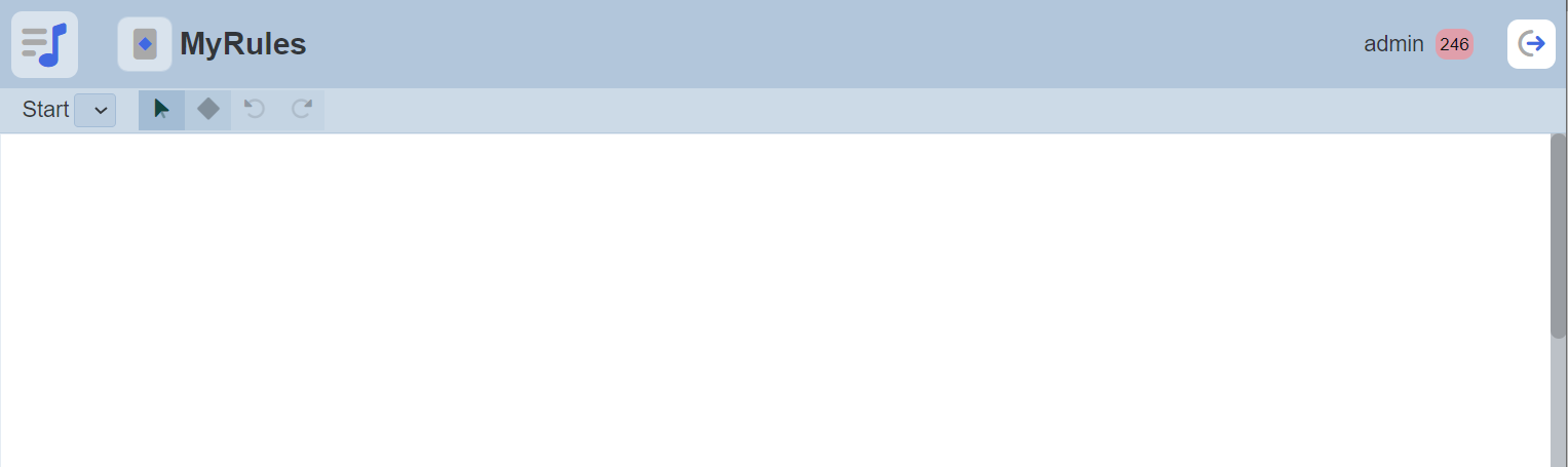
The top row contains a drop-down list which lists all the rules in the diagram and four buttons.

| Button | Description |
|---|---|
 “Select” button “Select” button |
Allows user to select the rule or the links in the diagram |
 “Create Rule” button “Create Rule” button |
Allows user to create a new rule in the diagram |
 “Undo” and “Redo” buttons “Undo” and “Redo” buttons |
Allows user to undo and redo actions done respectively |
The lower part is the design area, where user can place rules and flows.
Do note that if you are not the owner of the business rule, you can only view but not able to edit the diagram.
Rules
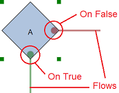
A rule can be called from an ETL chain and can also call ETL chains, allowing them to integrate seamlessly with the rest of the Ambience modules. Each rule is represented by a diamond shape. Each diamond decision point results in either a true (green circle) flow or a false (red circle) flow. The value of this decision point can be passed to another rule via a flow.
Add Rule
To add a rule, click on the “Create Rule” button at the top row and click on the any location in the design area.
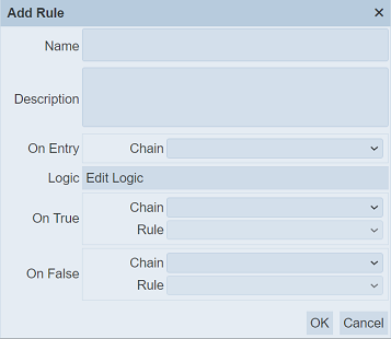
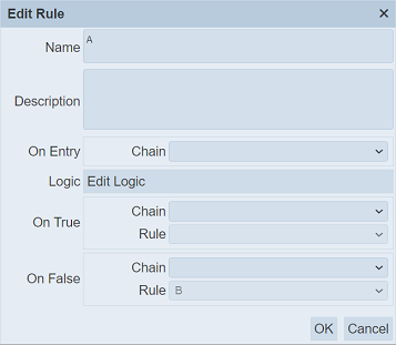
The “Add Rule” dialog box will appear.
| Field | Description | Mandatory | Input Type | Constraints | Default Value |
|---|---|---|---|---|---|
| Name | Unique name assigned to the rule. | Y | Text field | Any text (case-sensitive) | Empty string |
| Description | Brief description on the rule. | N | Text field | Any text (case-sensitive) | Empty string |
| On Entry | Executes the ETL chain defined. | N | Drop-down list | Select from drop-down list | Not selected |
| Logic | Allows user to add logic to the rule. | N | Dialog box | Returns true or false. | |
| On True | |||||
| Chain | Executes the ETL chain defined. | N | Drop-down list | Select from drop-down list | Not selected |
| Rule | Displays the rule connected to it if the condition returns true. | N | Drop-down list | Not editable. When the green dot of this rule is connected to another rule, the name of that rule is automatically displayed. | Not selected |
| On False | |||||
| Chain | Executes the ETL chain defined. | N | Drop-down list | Select from drop-down list | Not selected |
| Rule | Displays the rule connected to it if the condition returns false. | N | Drop-down list | Not editable. When the red dot of this rule is connected to another rule, the name of that rule is automatically displayed. | Not selected |
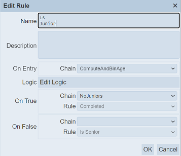
In the “Name” field, key in an unique name for the rule. Give a brief description of the rule in the “Description” field.
In the “On Entry” field, select the ETL chain from the drop-down list. This ETL chain will execute once this business rule is triggered.
To add a logic to the rule, click on the “Edit Logic” button next to the “Logic” field. See Edit Logic on how to add a logic.
In the “On True” and “On False” section each has two fields, namely “Chain” and “Rule”. The “Chain” field defines the ETL chain to execute when the logic returns true or false respectively. The “Rule” field is not editable. When the rule is connected to another rule via either green dot (true) or red dot (false), the name of the connected rule will be automatically displayed in this field.
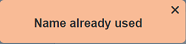
Click on the “OK” button to add the new rule. If a name is not provided or the name already exist, the relevant error message will appear.

Edit Logic
The “Logic” field allows user to define the logic for the rule.
To add or edit a logic to the rule, click on the “Edit Logic” button. The “Edit Logic” dialog box will appear.
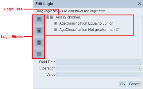
In the dialog box, there are four buttons on the left, namely Decision, And, Or and Not logic blocks. The logic tree on the right shows the logic for the rule.
If no logic is selected, the three fields at the bottom of the dialog box will be greyed out.
Add Logic
To add a logic, select the desired logic block and drag to the desired location in the logic tree. If the logic tree is empty, click on any location will add a new logic in it.
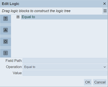
In the example above, “Decision” is selected. The three fields at the bottom becomes editable. Key in the desired value for the “Field Path” and “Value” fields. For the “Operation” field, select the desired operation from the drop-down list.
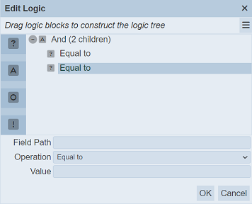
Select “Decision” and drag to the existing logic. The existing logic and the new logic will automatically “ANDed” together.
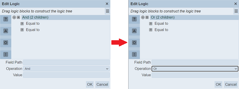
You can change the “And” or “Or” by selecting the “And (2 children)” and select “Or” from the drop-down list in the “Operation” field.
Click on the “OK” button to save the new logic.
Do note that the “And”, “Or” and “Not” logic blocks act on the “Decision” logic block.
Edit logic
To edit an existing logic, select the desired logic and edit the three fields as desired at the bottom of the dialog box. Do note that the “Not” logix block does not have any fields.
Click on the “OK” button to save the logic.
Delete Logic
To delete a logic block, select the desired logic from the logic tree and click on the  icon at the upper right corner of the page.
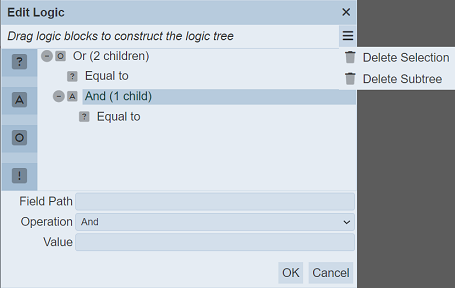
Select the “Delete Selection” option to delete the selected logic. Select the “Delete Subtree” to delete the entire subtree.
In the example above, selecting “Delete Subtree” will delete “And (1 child)” and the child below it.
If the highest level subtree is selected, in this case “Or (2 children)”, the entire logic tree will be deleted.
Edit Rule
To edit a rule, click on the button in the top row and select desired rule in the design area.
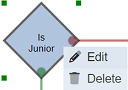
The selected rule will have its four corners highlighted. Either right-click on the rule to display a drop-down list and select the “Edit” option or simply double-click on the selected rule.
The “Edit Rule” dialog box will appear.
Edit the rule as desired and click on the “OK” button to save the changes.
Delete Rule
To delete a rule, click on the button in the top row and select desired rule in the design area.
The selected rule will have its four corners highlighted. Right-click on the rule and a drop-down list will appear.
Select the “Delete” option from the list. The rule will then be deleted from the deisgn area.
Flows
A flow links one rule to another and allows the flow of logic from one rule to another via the decision points of the rules.
Add Flow
To create a flow, click on the decision point (red or green circle) of the rule and drag to the target rule.
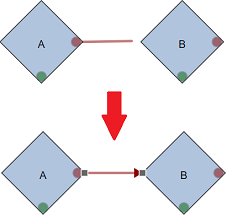
The colour of the flow will follow the colour of the decision point (i.e., red or green).
Once a flow is created between two rules, the “Rule” field in the “On True” or “On False” property of the starting rule will be filled with the name of the target rule, depending on which decision point is used.
In the example above, the false (red) decision point of rule “A” is used, thus the value of the “Rule” field of the “On False” property is filled with the name of the target rule “B”.
Add/Delete Node
The location of the rules may not be always aligned with each other. A slanted line will be drawn between these rules and it can become messy if there are lots of these lines.
Nodes can be added to the flow to allow straight lines to be drawn.
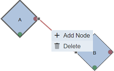
To do so, select the desired flow and right-click to display the drop-down list. Select the “Add Node” option from the list.
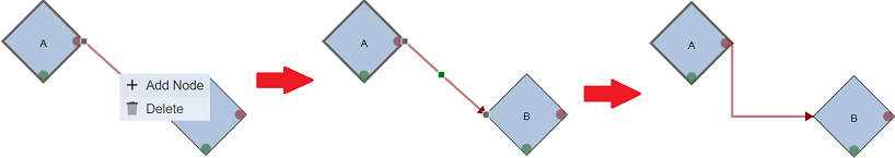
A green dot will appear on the flow. Drag the dot to the location desired.
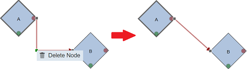
To remove a node, select the flow and to show the green dot. Hover over the green dot and right-click to display the drop-down list. Select the “Delete Node” option. The node will be deleted from the flow.
Delete Flow
To delete flow, select the desired flow and right-click to display the drop-down list. Select the “Delete” option.
Do note that once the flow is deleted, the value in the “Rule” field will be removed in the “On False” or “On True” property of the starting rule. In the case above, the value “IsSenior” is removed from the “Rule” field of the “On False” property of the “IsSenior” rule.
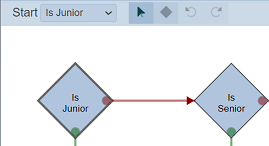
Start
The “Start” field at the top row allows you to select the starting rule. When an ETL invokes this business rule, the selected rule will be the first logic to be triggered. The border outline of the selected start rule is bold.
By default, the first rule created in the design area is selected as the start rule. To select another start rule, click on the drop-down list and select the desired rule.