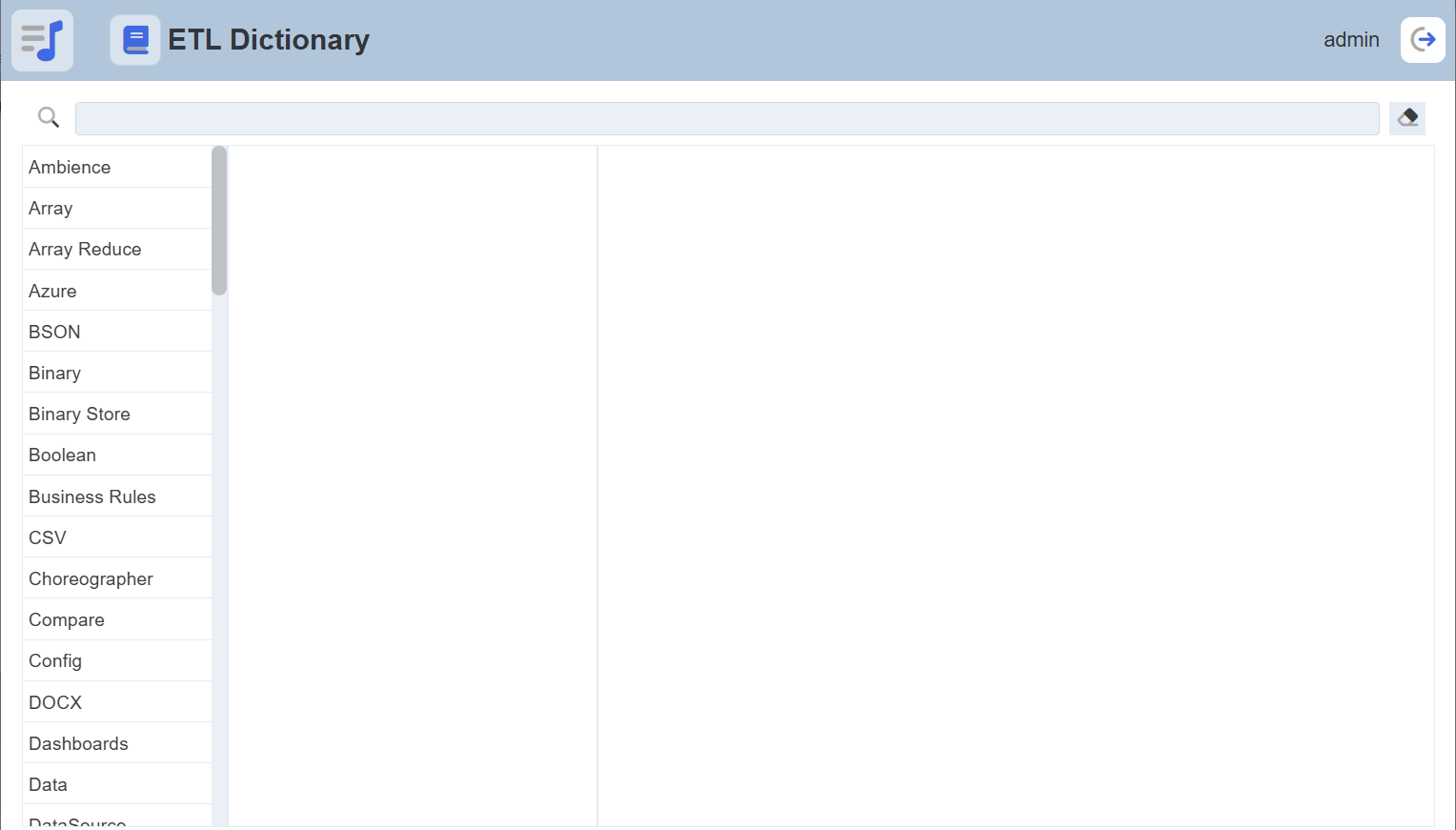
Steps Panel
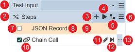
The Steps Panel is the second panel from the left in the ETL Designer page and it displays all the steps of a selected chainset. This also allows the user to run the chain or partially run it up to a specific step. Below are the different components of the panel:
| No. | Description |
|---|---|
| 1 | Allows input to be tested. |
| 2 | Allows inverting selected and deselected steps. |
| 3 | Allows adding new steps. |
| 4 | Runs the entire chain. |
| 5 | Shows the dependency tree. |
| 6 | Provides more actions that can be performed. Available options vary depending on the steps selected. |
| 7 | Checkbox indicating that the chain is selected. |
| 8 | Name given to the step. |
| 9 | Color assigned to the chain for aesthetic purposes. |
| 10 | Icon assigned to the step for aesthetic purposes. |
| 11 | Allows modifying a step’s parameter values and properties. |
| 12 | Runs the chain from the first step up to the step corresponding the this Run to Step button. |
| 13 | Indicates which chain is in focus. Selecting the step makes its Edit Step (11) button and Run to Step shortcut (12) button available. Also, the Run to Step option under More Actions (6) runs the entire chain up to this step. Hover over to display the icon that allows user to drag the ETL step to re-arrange its location. |
On this panel, the following features are available:
- add a new step
- move a step
- copy and paste a step
- modify a step’s parameters and properties
- run the entire chain
- partially run the chain up to a specific step
- disable a step
- delete a step
- set a color and an icon for an existing step
- test the input
Add Step
To add a new step, ensure that a chain is selected first. Click on the + Add Step button.

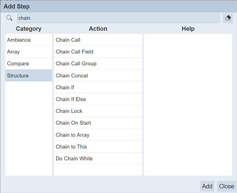
A dialog appears, prompting the user to select the step to be added. Steps are categorized into different step categories, which are located in the Category panel on the left. The Action panel contains the actual steps for the selected step category.
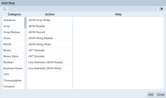
A search bar is available, allowing the user to select a specific step. Click on a step in the Action panel to select it. Documentation of the step is provided in the Help panel on the right. This includes detailed descriptions of what the step does. If applicable, other details such as step input parameters and acceptable values, output, notes, and other related steps are also included.
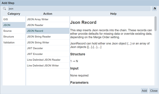
Alternatively, clicking on the Dictionary button on the top right corner of the ETL Designer interface opens the same descriptions on another browser tab.

Click on the Add button to add the step to the chain.
If more steps are needed, simply continue selecting other steps then click on the Add button. Click on the Close button after adding steps. If any step was added, closing would instantly open the Edit Step dialog box corresponding to the last step added. Do note that step input parameters are required to be entered and saved before closing the Edit Step dialog box, else the steps will not be saved.
Configure Step
Several steps have require input parameters, which are crucial in configuring the steps to result in the desired outcome. Different steps also have different input parameters.
Once the steps are added onto the chain, you will be required to review the input parameters before the Save button is available for you to save the steps. Clicking on the Cancel button before all input parameters are entered, results in all the steps being removed.
To configure an existing step, click on the 
Edit Step button corresponding the step.
The Edit Step opens and allows entering values for the step’s input parameters, as well as renaming the step. By default, the Step Type is set as the Step Name value. This value can be replaced with any text.
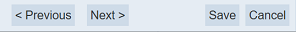
To save the changes, click on the Save button. To continue making changes on other steps in the chain without saving first, click on the Previous button to move one step up. Likewise, click on the Next button to move one step down the sequence. The Previousnavigation button is disabled for the first step. Similarly, the Next navigation button is also disabled for the last step. Clicking on the Cancel button discards the changes made.
Note that changes done would only be saved after clicking on the Save button. This means that if changes are made on several steps consecutively (i.e. using navigation buttons Previous and Next), then the Cancel button is clicked, all changes made since opening the Edit Step panel would not be saved.
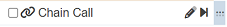
Chain Call Steps
There are special steps that run other chains within the same chainset. These steps, such as the Chain Call step, are found under the Structure step category.
The simplest of these is the Chain Call step.
In this example, there are two chains in the chainset:
- the
GenerateTextchain creates a text - the
SendEmailchain sends an email
The objective is to send the text out as the body of the email. This is a simple example that does not seem to benefit much from putting the email sending steps in another chain, but real world chains could be a lot more complex. The sample used intends to demonstrate how the data is passed from chain to chain during chain calls.
In this case, the Chain Call step is added to the GenerateText chain. The value of the Chain Name parameter is set to another chain, the SentEmail chain.
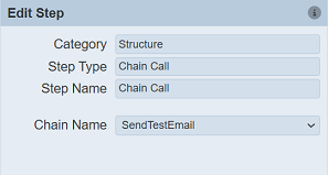
What it does is a straightforward call of another chain, as if the steps in the called chain are added to the chain doing the call. This means that the results of the sequence in GenerateText, before the Chain Call step, become accessible to steps in the called chain, the SendEmail chain.
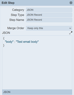
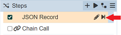
To demonstrate further, the JSON Record in GenerateText is set to contain a body tag.
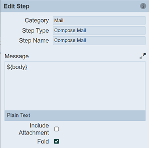
In the SendEmail chain, the Compose Mail step creates the document the body tag created can be referenced by tagging it as a variable ${body}.
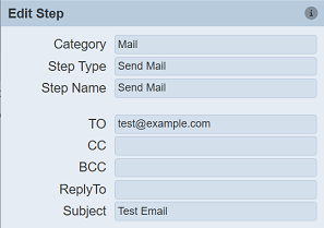
Assuming that the Send Mail step is configured properly (with at least 1 recipient), running the SendEmail chain alone results in an empty variable in the Compose Mail step, making the message (email body) empty.
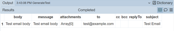
On the other hand, running the GenerateText chain alone passes the value assigned to the body field to the SendEmail chain, demonstrating how results can be passed to different chains through chain calls.
There are many other related steps, serving different purposes. For more information on these steps, refer to the Dictionary provided.
Run Steps
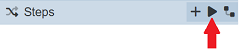
Chains can be executed manually on this interface one at a time. To execute all of the steps in the selected chain, click on the Run Steps button.
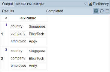
Right after triggering the chain to run, a record appears on the Output panel. Each run adds a record in the Output panel. The Results panel displays the actual results of the executed steps.
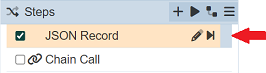
Running the chain partially is also available. Select a step by clicking on the row. An indicator appears on the right side of the row.
This can be done in two ways. Either click on the More Actions button then select the the Run to Step option, or click on the Run to Step button on the row.
Both would result in executing all steps between the first (top) and the selected step inclusively.
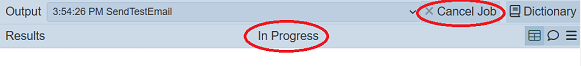
If the execution is ongoing, the result will not be displayed and the status In Progress is shown. A Cancel Job button will appear, allowing you to cancel the job.
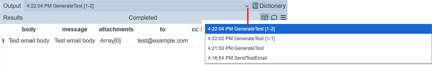
If the same chain or chain subset has already been executed before and is still listed on the Output panel, new records are labeled with a timestap appended before the chain or chain subset.
Modify Step Properties
Step properties, such as color and icon can be set through the options in the More Actions button. The process is similar to how these properties are changed for ETL chains.

Change Icon
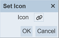
To change the icon assigned to a step or several steps, simply select the step/steps by ticking on their respective checkboxes. Click on the 
More Actions button then select the Set Icon option. A dialog box appears, prompting to select an icon. By default, there is no icon set for all steps. Click on the icon to assign one.
This displays the available icons that can be selected from.
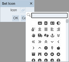
Entering the icon names on the search bar is useful to narrow down the options.
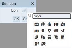
Select an icon then click on the OK button to set it.
Change Colour
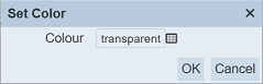
To change the color assigned to a step or several steps, simply select the step/steps by ticking on their respective checkboxes. Click on the More Actions button then select the Set Color option. A dialog box appears, prompting to select a color. “Transparent” is set as the default color for all steps. Click on the color to change it.
This displays the available colors that can be selected from.
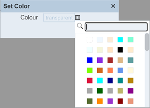
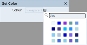
Entering the color names on the search bar is useful to narrow down the options.
Select a color then click on the OK button to set it.
Move Step
The order by which steps appear on a chain can be changed through the More Actions options.
Select a step or several steps by ticking on the checkboxes corresponding the step/steps. Click on the More Actions button.
There are four movements available:
| Option | Description |
|---|---|
| Move Down | Moves the selected step down by one step, swapping with the next step. This option is only available if only one step is selected. |
| Move Up | Moves the selected step up by one step, swapping with the previous step. This option is only available if only one step is selected. |
| Move to Bottom | Moves the selected step/s to the bottom of the sequence, making the selected step/s the last step/s of the chain. |
| Move to Top | Moves the selected step/s to the top of the sequence, making the selected step/s the first step/s of the chain. |
Disable Step
Disabling a step retains the step, its configuration, and properties, but excludes it from being executed in the chain. One or more steps can be disabled at once. To select steps, tick on the corresponding checkboxes. Click on the More Actions button then select the Disable option.
Disabled steps are grayed out. They can be modified even when disabled.
Delete Step
Deleting a step permanently removes it from the chain. One or more steps can be deleted at once. To select steps, tick on the corresponding checkboxes. Click on the More Actions button then select the Delete option.
Debug Logging
User can turn on debug log to view the results of the ETL steps. This can help user to debug the ETL chain, especially during initial setup.
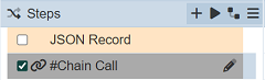
To do so, select the desired ETL step and click on the “More Actions” button and select the “Debug Logging On” option. The icon on the left of the ETL step will change to a heart icon, indicating the “debug mode”.
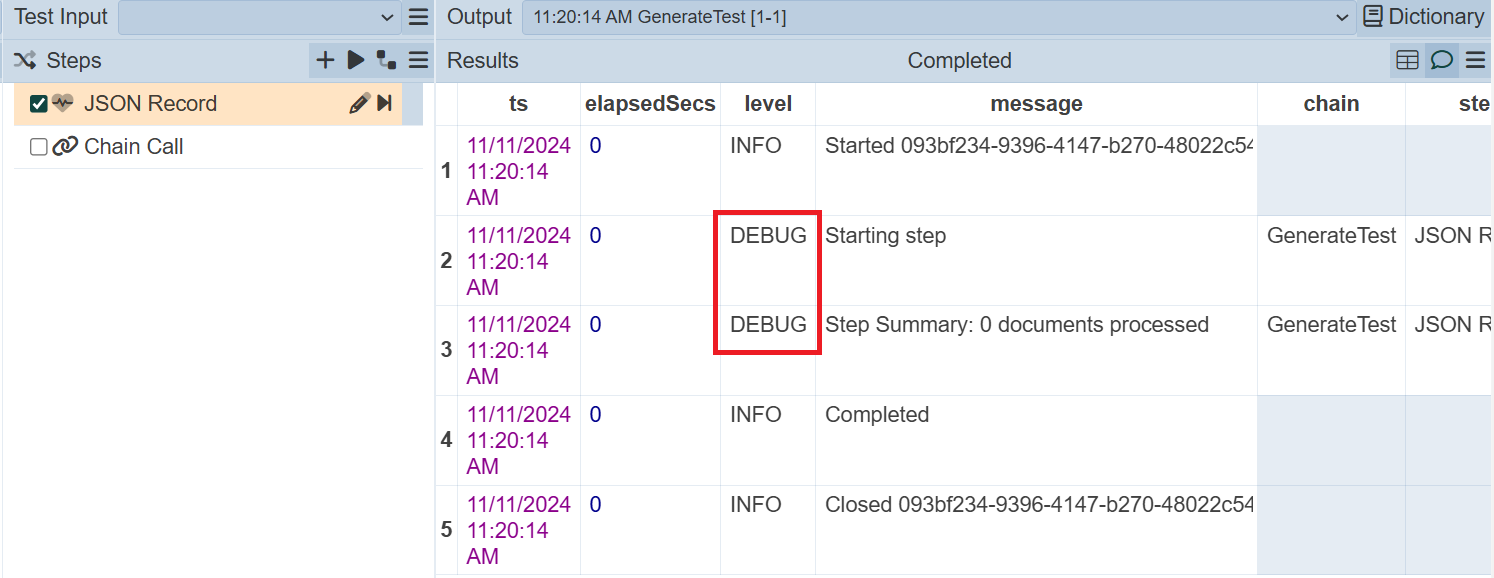
Run the ETL step and the debug log will appear in the Output panel.
To turn off the debug logging, click on the “More Actions” button and select the “Debug Logging Off” option. The icon on the left of the ETL step will revert back to the previous icon selected prior.
Show Chain-call Tree
Some ETL chain calls another ETL chain, thus creating dependencies.
To show the chain-call tree, select the desired ETL chain and click on the ![]() “Show Chain-call Tree” button in the Steps panel.
“Show Chain-call Tree” button in the Steps panel.
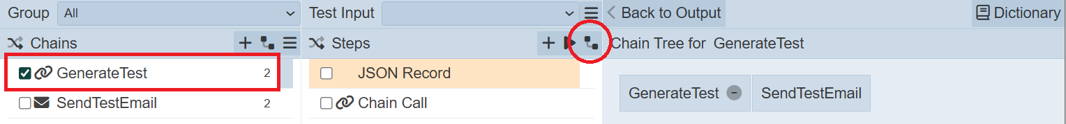
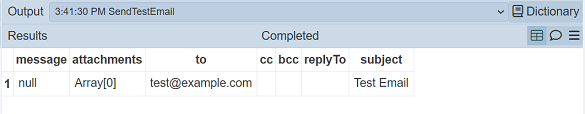
The dependency tree will be displayed in the Output panel. In the example above, the GenerateTest ETL chain calls the SendTestEmail ETL chain. Click on the “Bck to Output” button to show the Output
Test Input
The Test Input mechanism provides a way to record standard “unit tests” along with descriptions of the tests which are stored alongside the chains which makes it much easier for other suers to follow the design of their chain when they see the sample inputs. This is a better approach than placing a disabled JSON record at the top of the chain, as it need to be enabled/disabled. These test inputs are only used within the designer and will not affect the flow of the ETL when used live.
Multiple test inputs can be created and switch between them to see/demonstrate the different behaviour.
The “Test Input” field allows user to test the ETL step before using it. It will appear only when a ETL chain is selected.
Along with the More Actions button on the right of the field, allows user to add, delete and edit the test inputs.
By default, the drop-down list is empty. The only option available will be Add Test, since there are no test input to edit or delete.
Add Test
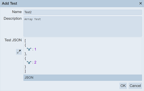
To add a test input, click on the button and select the only option Add Test. The “Add Test” dialog box will appear.
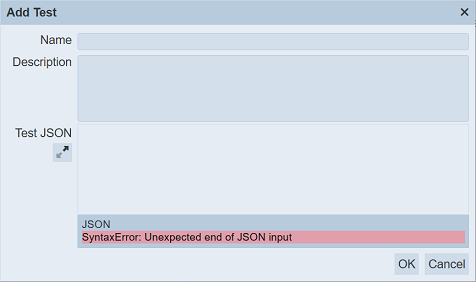
In the Name field, key in an unique name for the test input and a brief description in the Description field (optional).
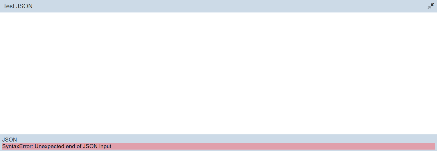
In the Test JSON field, key in the test input. The ![]() button next to the textbox allows you to maximise the textbox to a full screen. Error message will appear at the bottom of the dialog box if there is a syntax error in the JSON input.
button next to the textbox allows you to maximise the textbox to a full screen. Error message will appear at the bottom of the dialog box if there is a syntax error in the JSON input.
To revert back, click on the ![]() button at the upper right corner of the page.
button at the upper right corner of the page.
Click on the OK button to save the new test. A message will appear once the new test is saved successfully.
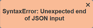
Error message will appear if any error occurs. Below are some examples.


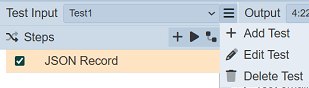
Edit Test
To edit a test input, select the desired test input from the drop-down list and click on the button. In the pop-up menu, select the Edit Test option. THe “Edit Test” dialog box will appear.
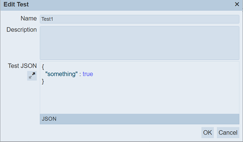
Edit as desired and click on the OK button to save the changes. A message will appear once the test input is saved successfully.
Delete Test
To delete a test input, select the desired test input from the drop-down list and click on the button. In the pop-up menu, select the Delete Test option.
A message will appear.
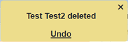
To undo the deletion, click on the “Undo” in the message and the test input will be restored.
Usage
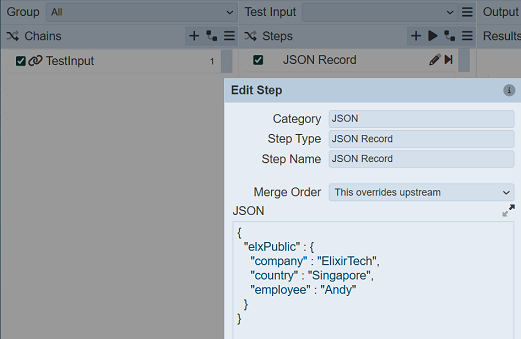
In this example, a simple ETL chain with one JSON record step is used.
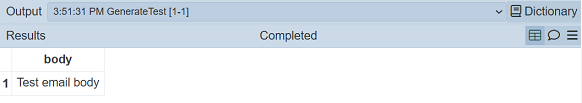
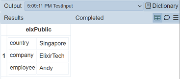
When the ETL step is run without test input, the result returns as such:
Create a simple JSON for the test input and label it as Test.
Select the Test1 from the drop-down list and run the ETL step again. The result returns with the test JSON as an input.
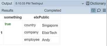
Create another test input and label it as Test2 This test input uses an array of records.
Select Test2 from the drop-down list and run the ETL step. The result return as below.