
Data Operation Processors
Data aggregation and transformation is performed by making use of the Data Operation processors. The Data Operation processors that are available in composite designer environment are:
The brief description of the processors are listed below.
| Processor | Description |
|---|---|
| Selection | Selects any item in the designer diagram. |
| Connects two processors together, allowing data to be transferred from one processor to another. | |
| Adds a DataSource processor onto the designer diagram. | |
| Joins two processors together. | |
| Sorts datasource records using specified criteria. | |
| Derive one or more new columns through computations on existing fields present in the datasource. | |
| Manipulates and groups database records to filter out those records which meet specific criteria. | |
| Concatenates records of two or more datasources. | |
| Serves two purposes: - Allows complex flows to be abstracted by defining modular sub-flows to aid comprehension of the diagram - Allows a single flow to be split into multiple branches based on conditions |
|
| Retrieves parameters from one input and applies them to another flow. | |
| Provides a generic processor that allows certain specific data processing tasks to be executed. | |
| Provides a cube component, allows generation of data results of your choice by defining multi-level dimensions and multiple measures using pre-defined functions. | |
| A pass-through output mechanism used to generate data that flows through it into different file formats. | |
| Used to generate processed data into different file formats. | |
| Provides a simple way to annotate composite diagram. |
Click on the blue links in the table to see more details on the processors.
Common Properties
Each processor and connector provides a pop-up menu and editable properties which can be accessed either through the popup menu, or by double-clicking the graphic on the diagram.
The options in the pop-up menu varies from one processor to another. There are two common properties in these wizard.

Name
One is the field “Name” which by default uses the name of the type of processor used. For example, a DataSource processor will have a default name DataSource, while a Sort processor has a default name Sort. It may be advisable to rename the “Name” field to a more meaningful name for easy identification and purpose of the processor.
Colour
THe other is the colour of the processor. The colour of the processor is shown in the background of the textbox of the “Name” field. All processors have the same default colour, which has a RBG colour code of F5DEB3.
You can change the colour of the processor by clicking on the “Colour…” button. A “Choose Colour” dialog box will appear.
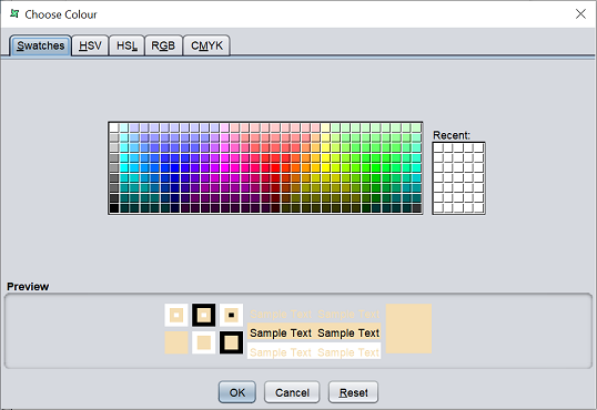
There are several tabs in the dialog box. Each tab represents a type of colour scheme. Choose the desired colour scheme and the colour you want to use. The colour chosen will appear in the “Preview” panel below. Click on the “OK” button to save the change or click on the “Reset” button to choose the colour again. To abort, click on the “Cancel” button.
As the processors uses the same colour by default, it is hard to read the designer diagram after more processor are added onto the diagram. It will also hard to find the desired processor among the many processor in the diagram, as they all have the same colour. Therefore it may be advisable to group the type of processor by colour. For example, DataSource processors are yellow, Result processor uses green, Join processors are light purple, etc. These colour will help identify the type of processors they are, and can help you organise the designer diagram.