
SubFlow
The ![]() SubFlow processor serves two purposes.
SubFlow processor serves two purposes.
First, it allows complex flows to be abstracted by defining modular sub-flows to aid comprehension of the diagram. In this role, the SubFlow processor acts like a subroutine call.
Second, a SubFlow processor allows a single flow to be split into multiple branches based on conditions. Each sub-flow may then perform a different sequence of actions, for example, storing the records to disk, deriving values where data is missing, etc. In this role, the SubFlow processor acts like a switch statement in a programming language.
Add SubFlow
To add a SubFlow processor, select the ![]() button on the menu bar and click on the location in the designer diagram. Use the Flow connector to connect the SubFlow processor and another processors together.
button on the menu bar and click on the location in the designer diagram. Use the Flow connector to connect the SubFlow processor and another processors together.
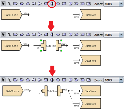
Note that the connector line from the SubFlow processor out to the DataStore is a dotted line instead of a solid line. A dotted line indicates that the output data is not available.
SubFlow Diagram
To link output data to the DataStore processor, double-click on the SubFlow processor and the subflow diagram will appear.
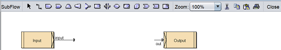
At the extreme left of the toolbar shows the name of the diagram, in this case it shows “SubFlow”. By default, there are twp processors in the SubFlow diagram, which is the Input and Output.
Two or more flows need to be joined to the Input to the Output, so that the records can be passed back to the parent flow. When acting as a subroutine, there is typically a single flow of processors between Input and Output. When acting as a switch, there are several flows in parallel.
In the example below, the SubFlow is acting as a switch, with two DataDrop processors are added onto the diagram.
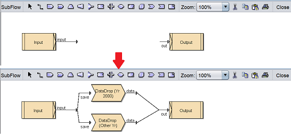
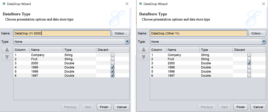
Double-click on the DataDrop processors and select the desired fields. The first DataDrop processor allows data Year 2000 to pass through while the second DataDrop processor allows all to pass through except Year 2000.
The Input graphic in the SubFlow diagram allows you to set a series of tests that are applied to choose between the different parallel flows. Double-click on the Input graphic to display the “Input Wizard”. Or right-click on the graphic to display the pop-up menu and select the “Properties” option.
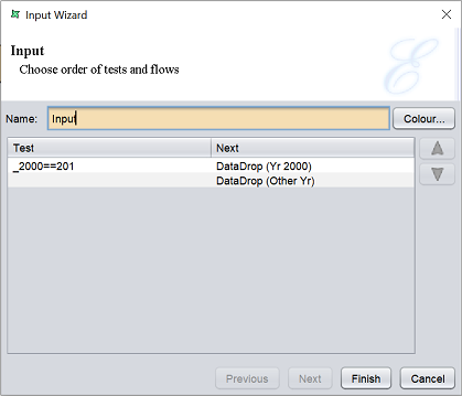
The Input tests proceed in order from top to bottom of the list. The first test that returns true, indicates that the record is passed to that flow. Subsequent tests are ignored. An empty test is considered true, and so all records that have not already tested true will pass to the first empty test flow.
You can change the order of the test by highlighting the desired row and click on the “Move Up” or “Move Down” button. If no test returns true, the record will be discarded. The test will be shown on the diagram as labels attached to the appropriate flow. The labels can be re-positioned by clicking them and adjusting the position of the handles.
Click on the “Close” button on the extreme right of the toolbar and return back to the parent diagram.
The dotted lines from the SubFlow processor out to the DataStore processors are now solid lines.
Edit SubFlow
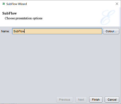
To edit the name and colour of the SubFlow processor, right-click on the processor and select “Properties” option from the pop-up menu
The “SubFlow Wizard” will appear, allowing you to edit the name and colour of the processor.
Delete SubFlow
To remove a SubFlow processor from the designer diagram, select the desired SubFlow processor, then either:
- Click on the “delete” key on your keyboard
- Right-click on display the pop-up menu and select the “Delete Graphic” option
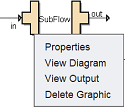
Pop-up Menu
Right-click on the SubFlow processor and a pop-up menu will appear.
There are four functions in the pop-up menu:
| Function | Description |
|---|---|
| Properties | Launches the SubFlow Wizard that allows you to edit the “Name” field and its colour. |
| View Diagram | Displays the subflow diagram. |
| View Output | Switches to the “Data” tab, which displays the records after the SubFlow operation. |
| Delete Graphic | Deletes the SubFlow processor. |